
Atmel AVR WiFi Radio WhereAVR Videoverlay EthIRnet IC-3200A Ballooning Lost At Sea Buzz-O-Matic Other Stuff APRS Tracker Generator Natural Gas Conversion Allstar Node 43710 Allstar USB FOB Local Radar 
|
The WhereAVR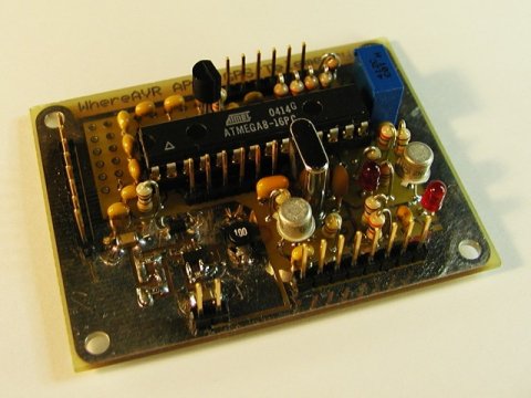
IntroductionThe WhereAVR is a small, lightweight, low-power, and low-cost APRS tracker with a full compliment of analog and digital I/O, as well as the ability to decode ax.25 packets. This allows for the reception of remote commands without the need for a "real" TNC. It is designed to hook directly to the speaker and microphone jacks of a handheld radio. One caveat, however, is that it currently doesn't have a spiffy configuration utility. I'm not into windows programming yet, so that feature will have to wait. :) Background InformationInspiration for this project stemms from recent activity with a local college, The University of Alabama in Huntsville, and their high-altitude balloon projects. As part of the electrical engineering senior design course, students propose, design, and build a series of experiments which are routinely lifted to 95,000 feet and above. A common package on every flight is a "communications package", which houses a radio, tnc, and battery pack. The TNC is a Kantronics KPC3 Plus which they use for GPS tracking and telemetry, as well as attempting to initiate a cut-down commands. The problem is that the TNC seems to be a point of contention, often causing much consternation. Since I too enjoy ballooning, I set out to design a board which could be interfaced to a GPS receiver and used as a tracker, could also send telemetry, and possibly even decode packets in order to command actions in the payload. Naturally, it would also have applications in remote monitoring such as weather stations, repeater control, actuation in difficult to access areas, etc. My goals for the board were for it to be cheap, low power, and light, as well as dependable and easy to reproduce. Oh, one more thing... I did NOT want to have to use an MX614! DesignHardware ComponentsFrom the start, I knew I would be designing the board around the Atmel ATmega8. And there are several reasons for this. I have had a lot of luck using the ATmega8 in prior projects and find it easy to program. It can be programmed in-circuit, has a variety of built-in functions, and runs blazingly fast. I had also found it to operate in extreme conditions just fine - a situation I'd be subjecting it to at -30 degrees Celcius on balloon flights. Finally, the price of around $3.00 each makes them nearly disposable. Beyond the microprocessor itself, there are a couple active components and a handful of passives. Some of the components are for direct microprocessor support - the 14.7456 MHz crystal being one. But most components are in support of additional features. They can be left off the design if the feature they support is not desired. I'll discuss the sections of the schematic further below: I have a couple LED's for transmit and DCD detect indication, and a level converter for the GPS receiver. There is also a section set aside for loading voltage dividers in order to scale inputs to send into the analog-to-digital converter. 
Audio ModulatorLike the other trackers, I chose to generate the 1200-baud audio signal using a straightforward resitor digital-to-analog ladder. By presenting a rising or falling binary value on the port connected to the resistors, an analog signal is generated. With the proper software, you can generate nice sine-waves used to modulate the carrier transmitted by a radio. The output of this d-to-a converter is hooked to the radio microphone jack. Audio "Demodulator"I also wanted to decode pakcet as well, remember? To that end I chose to build a simple zero-crossing audio signal detector using the internal comparator of the ATmega8. The incomming signal is capacitively coupled to the center of a voltage divider running from power to ground. This point is then connected to one of the camarator input pins of the microprocessor. This divider is set to a voltage very near to a 1.25v bandgap reference, which is contained in the chip and is chosen via software as the other input to the comparator. In this arrangement, every time the incoming signal passes through "zero" volts, the internal comparator triggers a software interrupt. For pure sinewaves, this "zero-crossing" occurs twice per cycle. By measuring the period between interrupts, I can tell the incomming audio frequency. GPS receiver level converterThis circuit is another straightforward design. All I do is use a single transistor as an inverter driven with the input from the GPS. Now that I think of it, I could leave out the pullup resistor as the ATmega8 has internall pullups. Oh well. :) Power Supply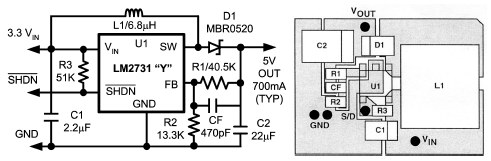
I needed 5 Volts to run the microprocessor and offboard GPS receiver. I decided I wanted a boost converter of some type for the design. It's easy to use a simple LM7805-variant to regulate a higher voltage to 5 Volts, but boosting sub-5 Volts is more challenging. So I figured it would do well to go ahead and provide a place for some surfance mount components to do just that. Turns out it was a good idea*. The design is based on a National LM2731 [pdf datasheet]. It is an efficient swtiching design. In lieu of explaning the circuit, I'll just refer you to the datasheet. I replicated their 5-Volt reference circuit and used their suggested board layout. It works great. *For the radio on balloon flights, I use an Alinco DJ-S11T. It is small and lightweight, and while it has a poor stock antenna, this can be fixed without too much work. What's nice though is that the radio holds three normal AA-sized batteries, and I use those three batteries to power the rest of the box by running some wires out of the radio case. During flights, I use Energizer Lithium batteries. Three of them can run the entire communications package, consisting of the radio, the WhereAVR board, and a Garmin GPS 18, for almost 24 hours. But with only three AA batteries, I only have at most 4.5 Volts to work with. The boost circuit of the power supply handles this fine. In fact, the board continues to run long after the radio ceases to operate. The radio gives up at 3.25 Volts, the WhereAVR runs down to 2.1 Volts. Printed Circuit Board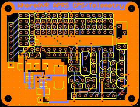
For this project I decided to design a board and have a few built. I figure a balloon payload is always at risk for loss if it can't be found after landing, and having a few spare replacements around takes the edge off losing a payload. In the downloads section below you'll find a couple board files in ExpressPCB format. One card holding two boards meets their "Miniboard" format. That way I only pay $10 a board. You'll also find a file showing just one board. I included this one to show it oriented upright for easier viewing.  Software ComponentsThis is where all the cool stuff happens. Software in the WhereAVR is written totally in C and compiled with the freely available GNU GCC compiler. The compiler is part of the WinAVR suite of development tools for the Atmel AVR and it couldn't suit my needs better. It is an open-source program, comes with great documentation, and support is available through many groups on the web. At the bottom of this page you will find a link to all of the source code for this project. In it you may find I went overboard with commenting my code, but I can't help it. Not only can it help others learn a few tricks, but it also helps me years from now when I look back over it and ask, "What on earth was I thinking when I wrote this?" Sinewave GeneratorThe MARK/SPACE modulation tones generated by the WhereAVR are born in the digital world. Since the D-to-A converter is only 4-bits, the sinewave values are approximate, and range from zero to 15. Zero is 0 Volts, and 15 is 5 Volts. In a spreadsheet, I set up a mock sinewave spanning this zero to 15 integer spread. It was split into 16 equally-spaced segments (ie. each segment is 8/pi) and for each segment, the nearest integer approximation to that value was chosen. An interrupt service routine is programmed to increment to the next value each time it is called. To get a MARK sinewave at 1200 Hz., the routine is called at 19,200 Hz. And likewise the routine is called at 35,200 Hz. to generate the 2200 Hz. SPACE tone. Refer to the source code linked below for more details. ax.25 Sentence CreationI feel like referring you to the source for this section, so I will. There you will find an ax25.c file which should explain most of what is going on. But as a primer, I will direct you to two other references. One is the APRS101.pdf document. It is definitely something you want to check out as it defines all of the standard APRS messages. Secondly, I must point out that my source file grew out of the one by Zack Clobes, W0CZ, a memeber of RCKARA. It's hardly recognizable since I essentially rewrote it to make sense to my brain, but his work is definitely in there. As is John Hanson's, W2FS, who I believe wrote it originally. Packet Demodulation and DecodingRecall what I began explaining in the hardware section. There I mentioned that when an input signal is conditioned and sent into the analog comparator, I am able to detect zero-crossings of the signal. And recall how a tone (a sinewave) crosses zero twice per cycle. [Draw one and prove it to yourself.] Well as it turns out in 1200 baud packet for the two tones MARK and SPACE (or 1200 Hz. and 2200 Hz., respectively), at least one cycle of each tone is contained in the incoming audio signal for each tone toggle. When the zero-cross triggers an interrupt in the micro, I take note of the time which has passed since the interrupt was last called. And based on this time, I can tell the frequency of the signal which is input. Amateur radio packets are easy to generate, but a challenge to receive. Each bit in each byte is sent least significant bit first, and each bit is prepresented as a toggle, from MARK to SPACE or SPACE to MARK, for the value of zero, or the absense of a toggle for a 1. The MARK/SPACE toggle rate for all zeros is 1200 Hz. But what if we want to send all ones? Well, then after every five consecutive ones, a "filler" toggle must be inserted. This keeps the receiver synchronized to the transmitter. Each time the comparetor interrupt occurs, it additionally checks to see if the last tone detected is the same as the new tone detected. If it is, it sets a "tone just toggled" variable to true. Another timer-based interrupt service routine, which runs at 9600 Hz.) looks for "toggle" to be set and uses this to stay synchronized with the remote transmitting station. After each "toggle" it starts a sampling routine which waits 1.5 bit periods before it samples the next bit, and then each bit after that is sampled after one bit period has transpired and so on... until ANOTHER toggle is sensed, which then serves to keep everything in sync and it all starts over. If the toggle occurs after five consecutive ones, it is ignored since it is filler. If it occurs after six consecutive ones is is recognized as a special "Flag" character, which precedes valid ax.25 sentences. Ok, I'll be the first to admit that I butchered the explanation. I will gladly post a link to a better explaination here if someone points me to one. Since I'm talking about links, here's a link to Mike Berg's page. His page was the inspiration for this project. Unfortunately, my assembly is so rusty that I didn't get much from his source, but I know it works great because I have witnessed a chip programmed with his code in action. Message Generation and HandlingThe rest isn't much more than messing with character arrays. I store my "canned" transmit headers, one with a path and one without, in EEPROM. I also store status text and whatnot in there. You'll see the code for reading those sections in the source. When creating and decoding sentences, it's important to remember that all the bytes in the header are shifted one bit to the left. And only the last byte has bit zero set, signaling the end of the header. This took me hours to figure out. Actually, there are hundreds of hours in the code, but that was the one "brainslap" realization. Currently, the WhereAVR is programmed to acknowledge any message consisting of one character and a request for acknowledgement. It also sends all the valid decoded packets it receives out the serial port pin. This was super-useful for debugging, and pretty cool to boot. :) TestingI addition to hundreds of hours of bench operation, the WhereAVR has flown on three flights above 90,000 ft The first time it worked up to altitude, but stopped working at balloon burst due to a presumed power faliure. On the second flight it worked flawlessly, transmitting it's position and acknowledging commands during the entire flight. Unfortunately, it became almost inextricably caught in a tree upon return. After a tortuous 45 minutes of hell at the end of a tree branch being violently shaken, the eyebolt was finally torn from its styrofoam enclosure. Despite this, the board and the tattered box's contents continued operating for another 15 hours. The third flight was also a successful test... though I'm afraid I'll never get the board back as it floated out over the Atlantic and was going 111 mph on a beeline for Bermuda. :) ConclusionAll in all I feel I was successful in accomplishing what I set out to do, and that was to essentially build my own no-frills TNC with as little as possible. I'm continuing to make improvements as time goes on. Eventually, it might be nice to reduce the design to surface mount to save further on weight and ease of construction. Yes, I find surface mount easier than through-hole. Also, I have only used little more than half of the 8K program space of the ATmega8, so there's tons of space left in there for all kinds of fun bells and whistles. FeedbackI welcome questions and comments. E-mail me at (that's 'me@') my website name. DownloadsSource: WhereAVR_18JUL2005.zip Schematic File: ax25.sch Board File: Single Board File: Double (as ordered) |
|---|
